


We’ve all heard and probably experienced the feeling of empowerment that happens when making. If you want to amplify that empowerment feeling - try making your own maker tools.
For a fun and inspiring example of this, check out where Thomas Thwaites documents his attempt at making a toaster from scratch -- including mining raw materials.
Building your own tools does not have to as daunting as Thomas Thwaites searching for copper mines in The Toaster Project, (a fun read)
It can include finding a kit like the 3D printer kits that Ellen and Lucie used to build their 3D printers. Or it can mean scouring the Internet for DIY videos and tutorials until you find one that will work for you.
In today's March is for Making inspiration (30 #makered inspirations in 30 days), we’re going to share how a group of teachers got together at the Generator for an empowering maker session and built their own acrylic bender.
Video: Teachers building maker tools at Generator - Burlington's maker space
After being inspired by Sarah Sutters workshop - Amazing Acrylic at Create Make Learn Summer Institute 2017, where we learned to bend acrylic to create fun maker projects, many of us wanted our own acrylic bender for our school.

So we stopped wishing we had one and picked a date to come together at the Generator (Burlington’s community makerspace) to make one, or two or three!
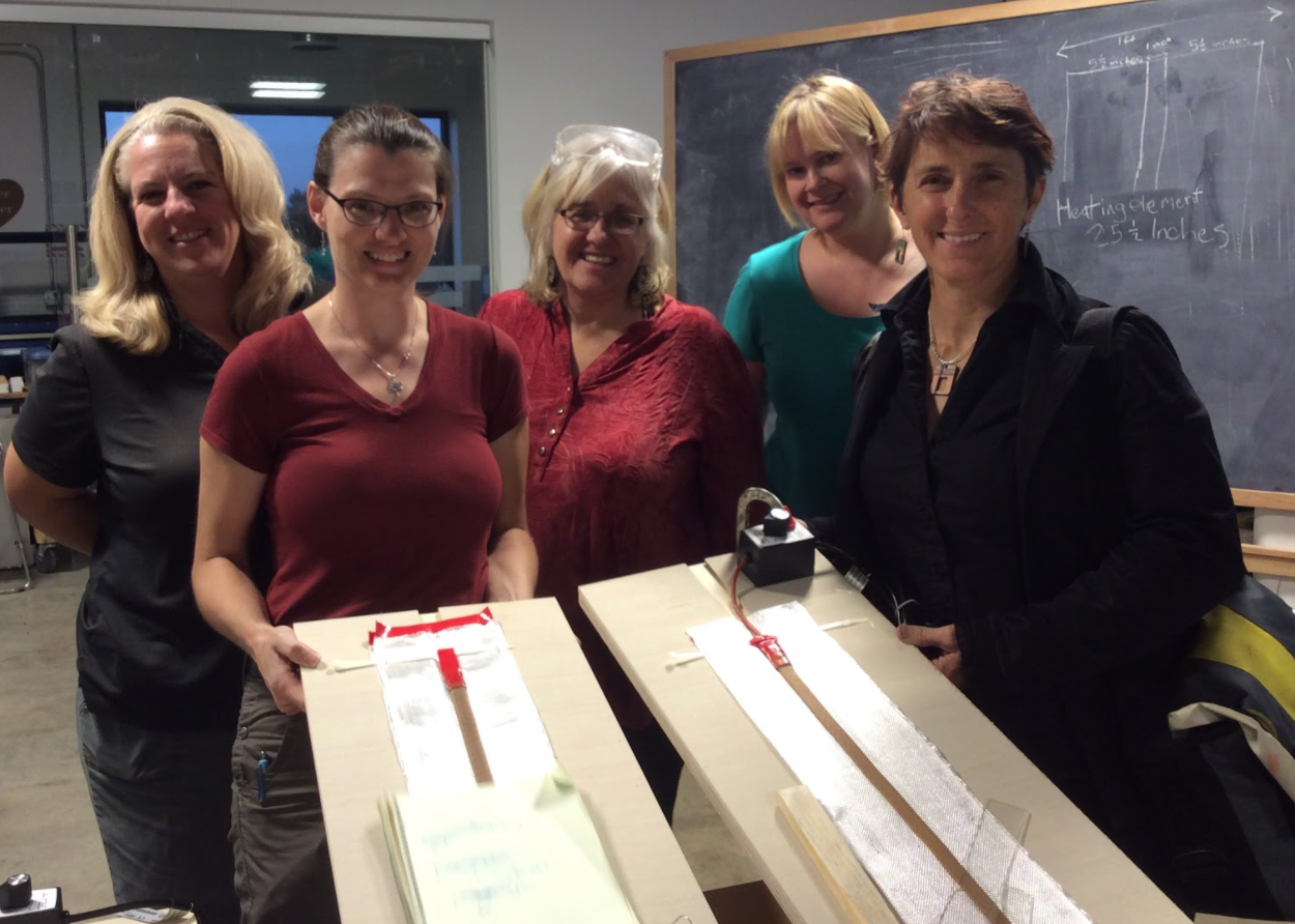
Vermont Educators ( Leah Joly, Caty Wolfe, Lucie deLaBruere, Jill Dawson, and Jean Cherouny) feeling empowered after a fun evening of making our own acrylic benders.
Here’s some notes and pictures of our build
(Special thanks to Jill Dawson for documenting our build)
(Special thanks to Jill Dawson for documenting our build)
First the research:
Honestly, many of the DIY videos out there on making an acrylic bender were downright scary.
Who wants an exposed nichrome wire at 800 degrees in their classroom?
Finally we found a a build video from BriskHeat which used some of their heat tape and a control dial to help regulate the temperature.
Reassured that we could create a safe tool for our students to use, we proceeded to order and organize the materials.
Supplies:
- 1 X BriskHeat flexible Silicone Rubber Heat Tape with Time Percentage Dial Control (BSAT) (We used the 72 watt model which measures approximately 2 feet in length and one inch in width; if you choose a different model for your build, you may need to modify the dimensions of your materials).
- 1 piece of ¾” sanded plywood, cut 1 foot wide by 3 feet high
- 2 pieces of ¼” sanded plywood, cut 5.5” wide by 3 feet high
- A little more than 2 feet of heavy tool aluminum 36 gauge, cut 4” wide
- Approx 5 feet of 6” wide boat fiberglass or fiberglass tape
- Wood glue
- Electrical tape or duct tape
- 2 zip ties (between 6-10 inches long
A little more research on safety
Since we were planning to use these with students, one of our biggest concerns was safety. Special thanks to Tyler Feralio, for helping us find, modify, and test this acrylic builder plan from Brisk Heat.
And many thanks to Generator member and leader in the electronics lab, Leisa Fearing, who helped us better understand how the Brisk Heater worked and whether it would indeed be safe to use with our students.
Step 1: Prep Tools & Supplies
Video: Leisa Fearing helps us understand our build
Step 1: Prep Tools & Supplies
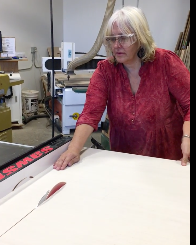
To get started we assemble your tools and supplies.

Lucie and Jean headed to the wood shop where we cut the plywood to size.
We modified the dimensions of the Briskheat build to make our acrylic bender more portable and easier to store. After doing a little math we decided we would need
- 1 piece of ¾” sanded plywood, cut 1 foot wide by 3 feet high
- 2 pieces of ¼” sanded plywood, cut 5.5” wide by 3 feet high

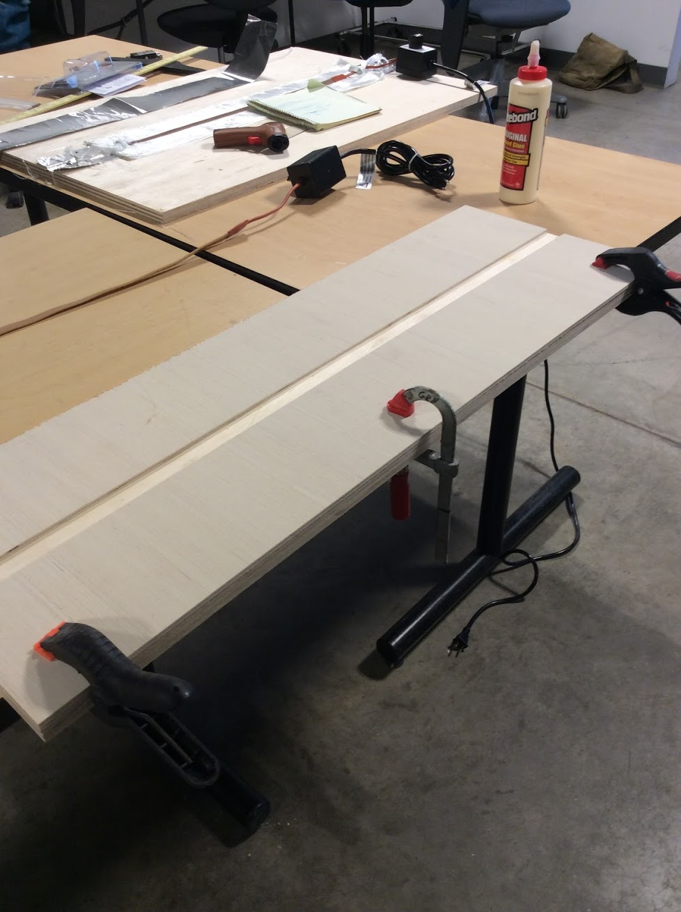
Step 2: Assemble the Base
Our next step was to position the two smaller ¼” plywood to the top of the ¾” thick leaving a 1” gap in the middle to house the strip of silicone heat tape.
Note: If you are using a BriskHeat model with a wider strip of heat tape, you will need to adjust the dimensions of your ¼” plywood boards. This may be easily accomplished by measuring your heat tape at its widest point, adding a little to accommodate for the fact that you will also be adding fiberglass and aluminum in the groove to protect the wood from being scorched.

Once we were comfortable with how our boards were to be laid on top of each other, we applied some wood glue with a paintbrush.
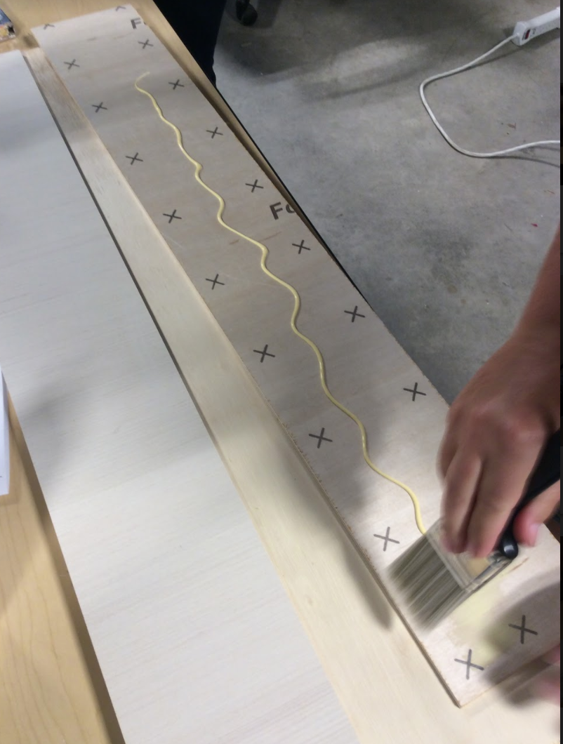


We grabbed any wood clamps we could find to hold our project together while we went on to the next step.
Step 3: Add Aluminum and Fiberglass to the Channel to Support the Heat Strip

The next step was to lay some heavy tool aluminum and some fiberglass tape in the groove to prevent the heat strip from scorching the wood when it heats up. The hardest part was finding the right size of fiberglass tape. We eventually found this in a marine shop that carries boat supplies.
We ended up using a little more than 2 feet of heavy tool aluminum 36 gauge, cut 4” wide and approximately 5 feet of 6” wide boat fiberglass or fiberglass tape
To determine the exact dimensions of the 36 gauge aluminum tooling, we took a measurement from the free tip of the heat tape to the start of its rectangular counterpart next to the power cord.
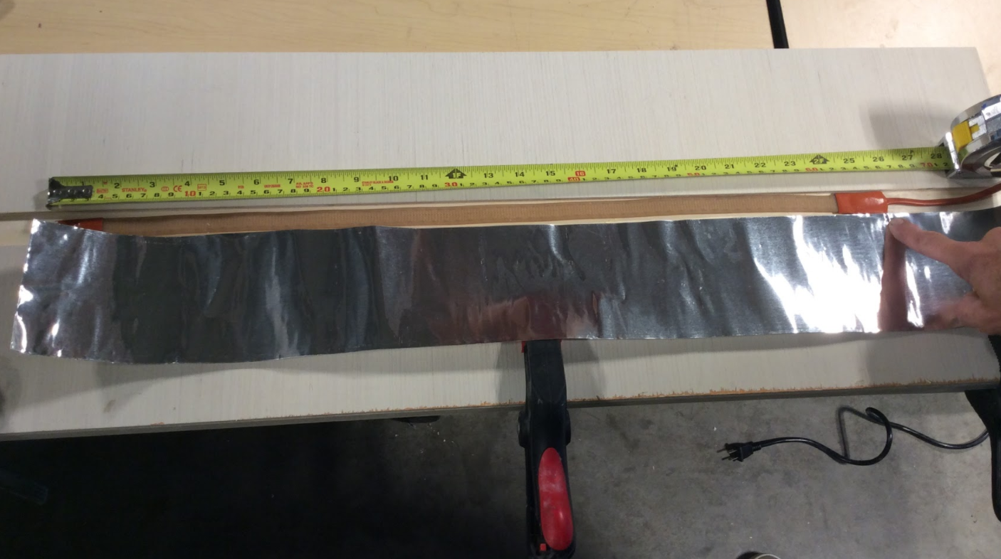
Using scissors, we cut a piece of aluminum that was 4” wide and 25.5” long. We wanted the aluminum to be long enough to support the heat strip, without extending much beyond that.
Center the width of the aluminum along the channel between the ¼” boards. We chose to position the aluminum about 2 inches from one end of the board and 8 inches from the other end, to give ourselves more room to house the control dial for the heat strip.


Use your thumb or the hard end of your paint brush to press the aluminum into the channel.
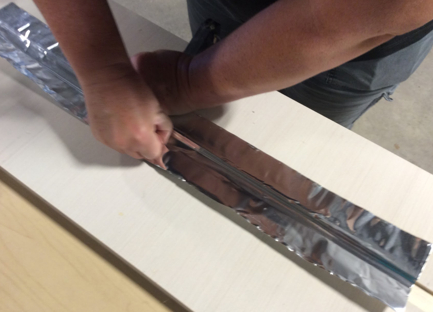
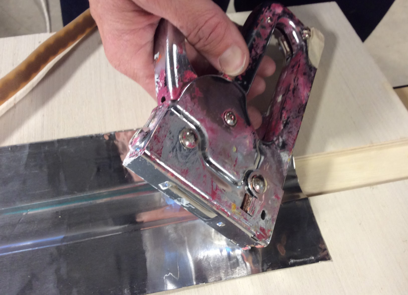
Secure the aluminum into place with the staple gun.
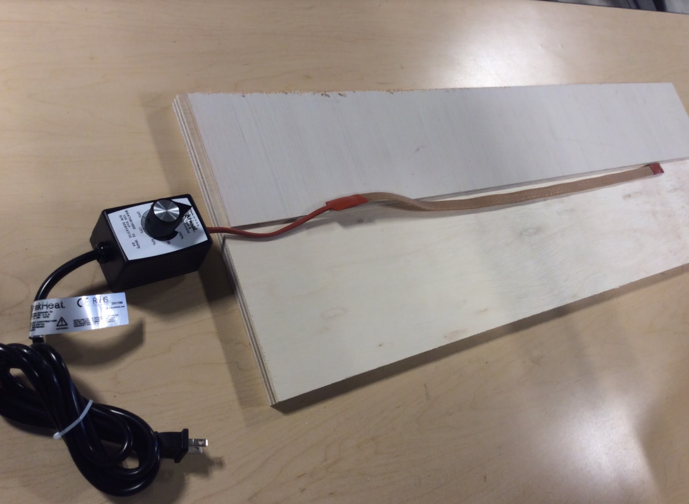
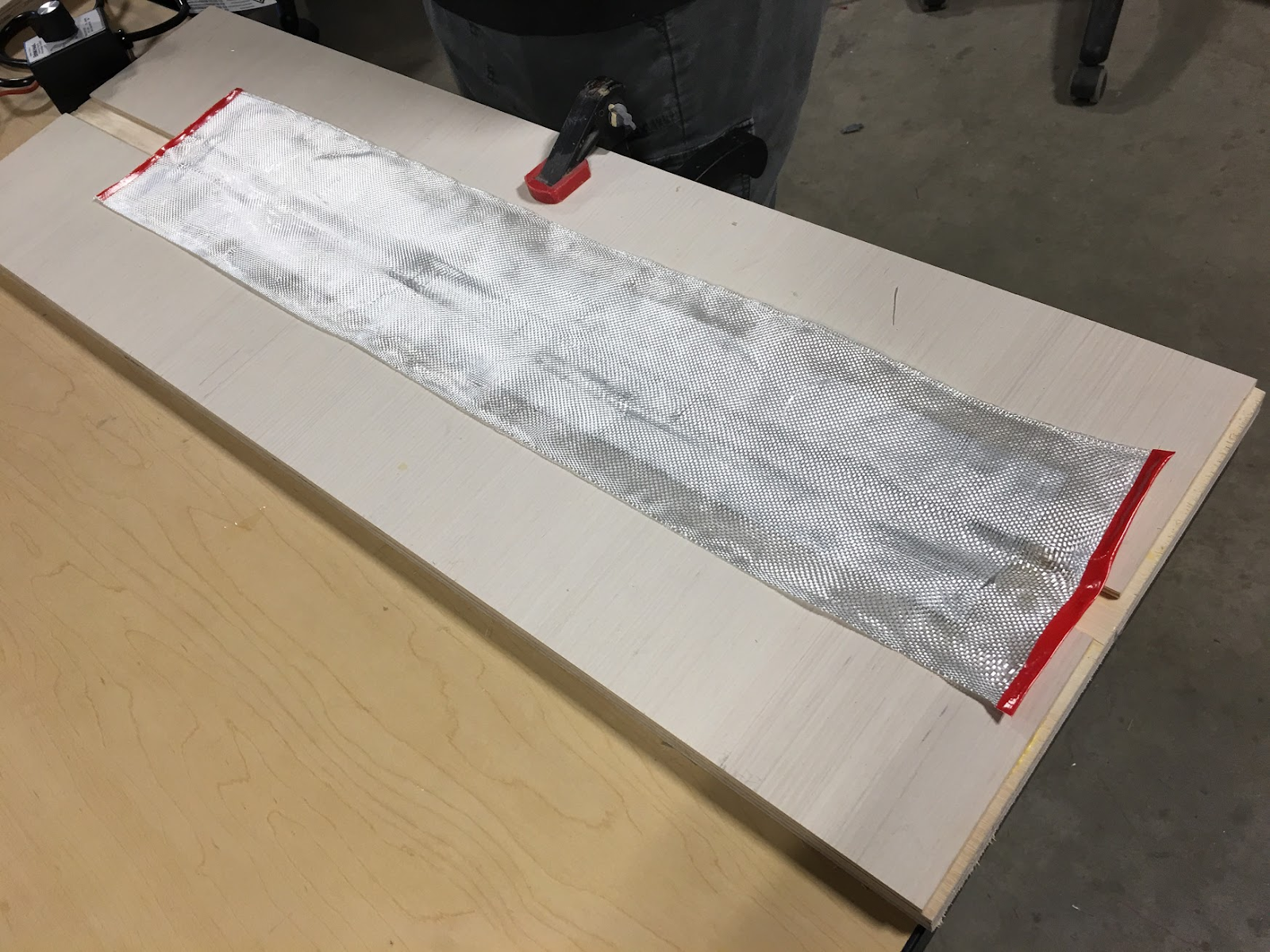
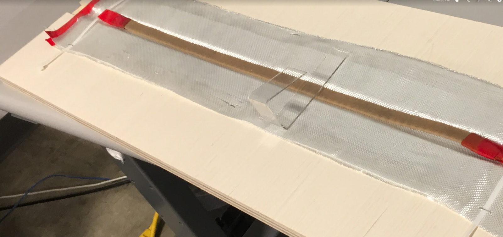
Here’s what your build should look like so far! See how the strip heater fits neatly in the groove.

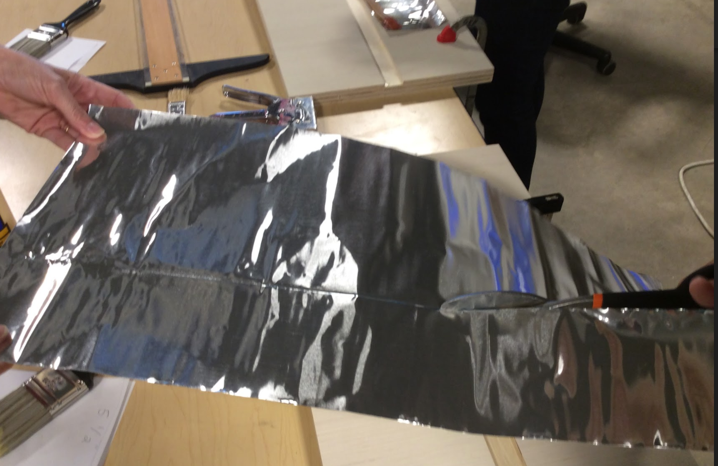
Step 4: Add Fiberglass
Our next step would be to cut some fiberglass to add an extra layer of protective insulation.
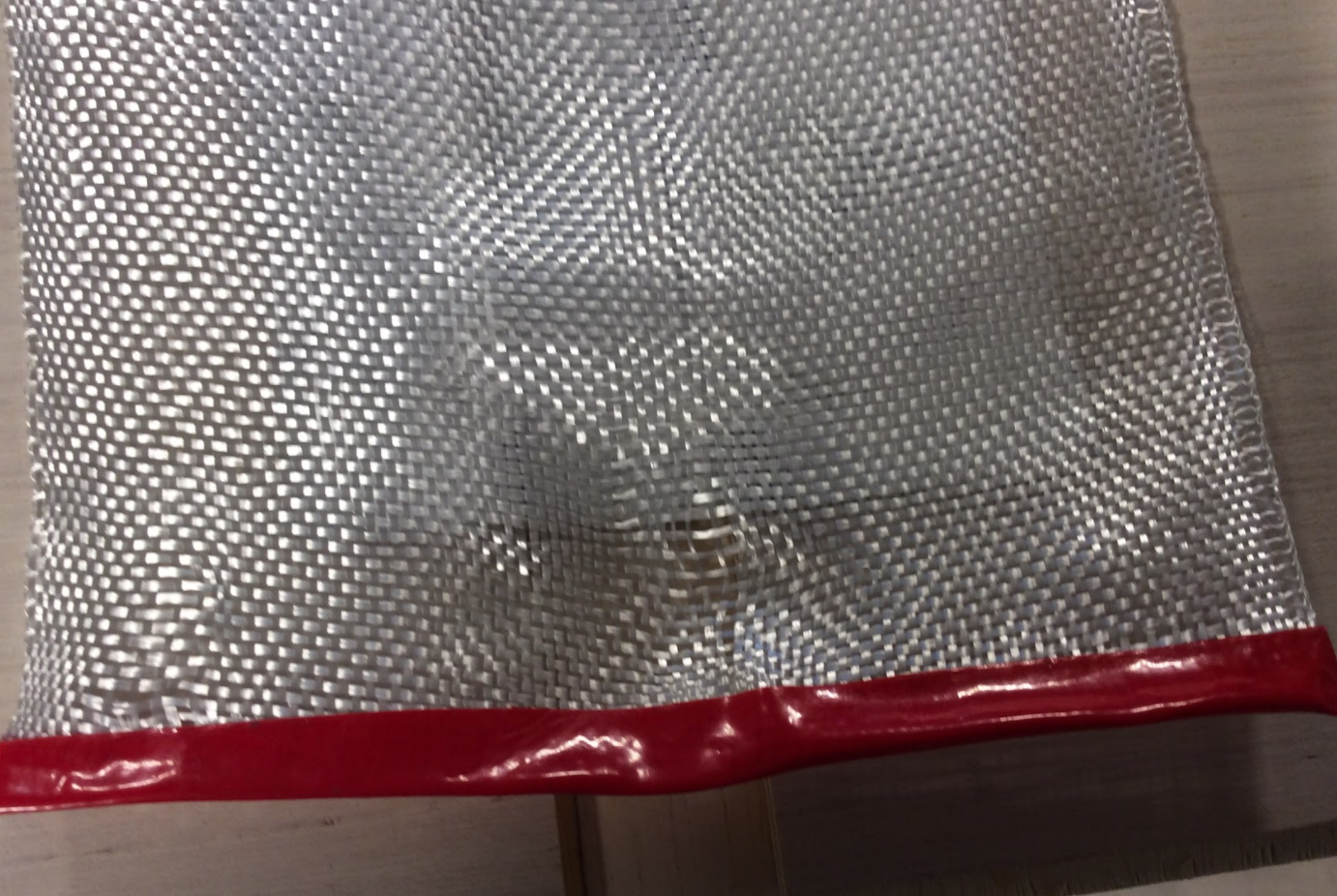
This proved to be one of the harder step. Fiberglass is not easy to work with. It unravels like crazy.
Note: Please read this before cutting your fiberglass
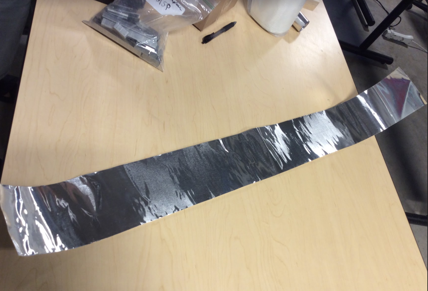
To determine the dimensions of the 6” wide fiberglass (or fiberglass tape), we took the length of our aluminum (25.5”) and added another 4 inches or so. This left us with close to a 30” strip of fiberglass.

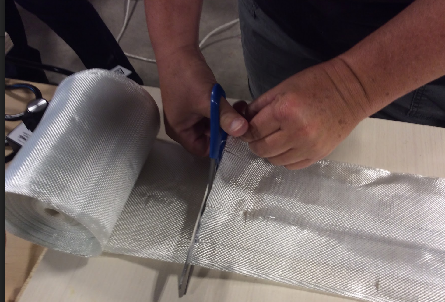
We then neatened up the edges by trimming them with scissors and reinforced each end of the fiberglass with electrical tape. Duct tape would also work.

After we’d done this, we realized that we should have DOUBLED the length of the fiberglass, to add more insulation.
As a result, we simply cut another 30” strip of fiberglass and repeated the process, using more electrical tape to connect the two pieces of fiberglass at both ends.
If you’d prefer to cut one piece of fiberglass and double it (and then apply electrical tape to only one end, that is another option).
Position the fiberglass so that it completely covers the aluminum channel. Press the fiberglass into the channel (with the heating tape nested inside of it), and use the staple gun to secure it into place.

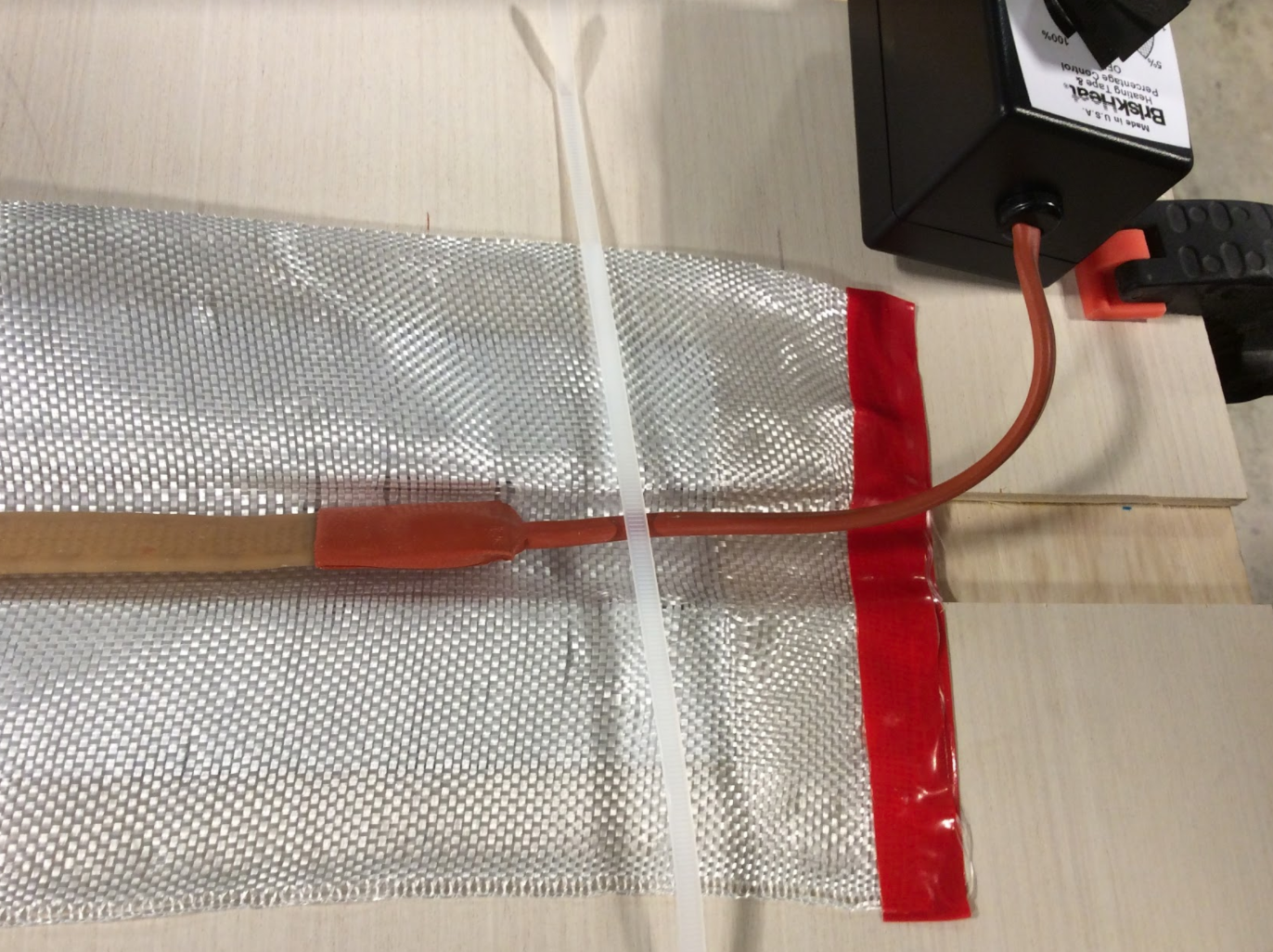
Step 5: Attach Zip Ties to Secure the Heat Tape
At this point we noticed that our heat tape didn’t stay in our groove the way we had hoped. After lots of brainstorming solutions to this and experimenting, we finally came up with a way to keep the heat tape from slipping around.
First we wrapped the free tip of the heat tape with one piece of electrical tape, and then used another piece of electrical tape, wrapped around the center of a zip tie, to attach it to the heat tape.

We repeated this with the rectangular end of the heat tape closest to the power cord.


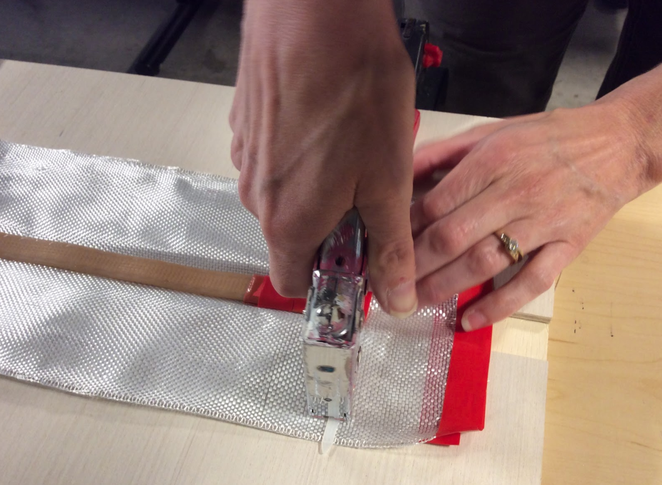
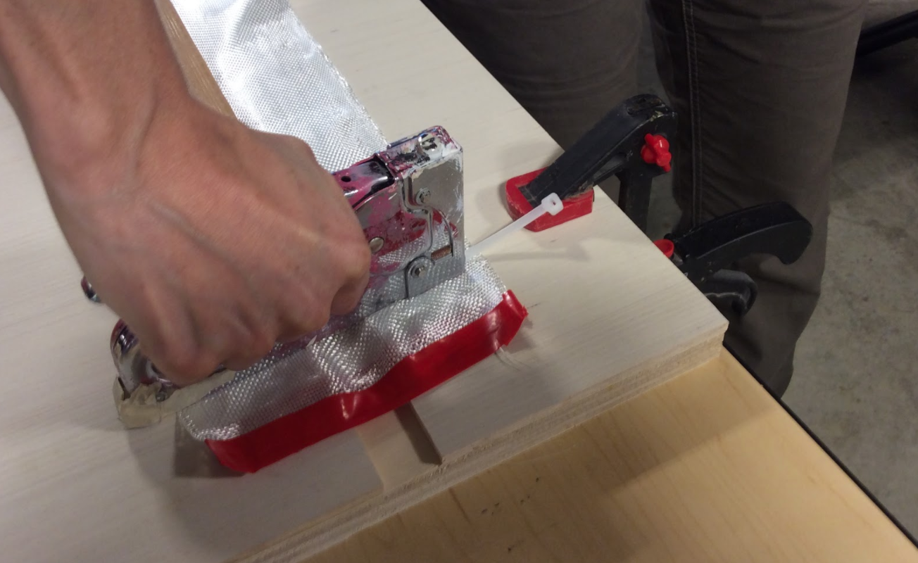
Lastly, we used a staple gun to secure the zip ties in place.
You might engineer your own solutions to keep the heat tape in place.
Step 6: Power it Up and Bend Some Acrylic
It was finally time to power up our newly assembled acrylic bender and test it.
Lay down a strip of Acrylic and hold it there until the crease becomes soft enough to bend it to the desired angle.

We found that a temperature gun came in handy to test where we had to position the dial so that the temperature would be around 200 degrees. It also let us know when our acrylic was just the right temperature to easily bend.
Remove your piece of acrylic from the heat source and hold it still while it cools to the point where it will keep its new shape.

And Voila!

In tomorrow's post, we’ll take you into Caty’s classroom to see how she and her students used the new acrylic bender that their teacher made herself!
No comments:
Post a Comment